
Catsperch “Frazier Pro” Kit
I took the following pictures during final assembly of a Finished CATSPERCHTM “Frazier Pro” Observing Chair I recently sent to a gentleman in Texas. I thought I’d share them with those interested in the “Kits” and show the step by step process, which can be completed in an evening. Also, if you are assembling a Kit yourself you will find these pictures useful as a supplement to the assembly instructions that comes with the Kit.
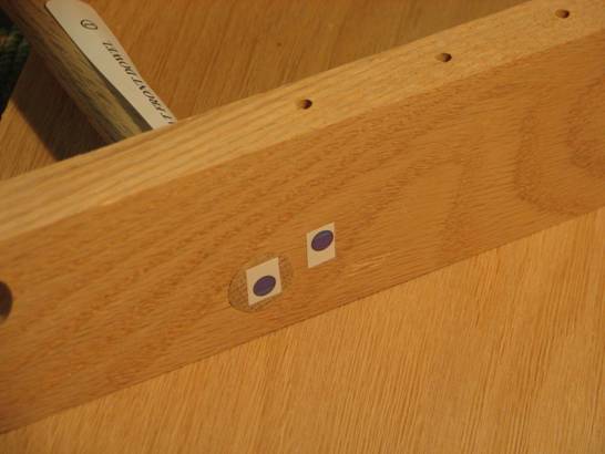
The parts for your CATSPERCHTM Observing Chair kit have been predrilled in an assembled configuration to facilitate a “good” mating fit during construction. Each part has been labeled for ease of identification and in some instances additional information about the orientation of the part (ex: “This side out”) should be noted. Some labels have also been annotated with reference numbers to associate the part orientation relative to the mating part labeled with the matching number. The correct end orientation of dowels is also indicated with color matching dots.

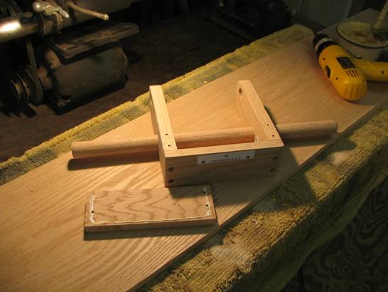
Leg Assembly
Build & sand the Leg Assembly first as you will use the leg assembly with the leg swivel dowel to help insure correct positioning of the notched boards on the main board.

1) Apply glue into each of the ten (10) biscuit grooves on the edges of the leg hinge support board and in the matching grooves on each of the leg sides and press the biscuits into the leg sides. (Tip: You don’t need to fill the slots.)


2) Run a 1/8″ wide bead of glue along the entire length of the hinge support board grooved edges and coat the ends of the square spacer block with a thin layer of glue.


3) Be sure the hinge support board is positioned with the 2 hinge mounting holes toward the square spacer block and facing the inside of the leg assembly as shown and that the screw holes in the ends of the square spacer block are aligned with the mating holes in the leg halves.

4) Press the leg components together. Use the leg dowel (DO NOT GLUE) as an alignment aid by inserting it through the holes in the leg halves. Insure that the ends of the leg sides and the hinge support board are flush. Check for square with a tri-square. Clamp the assembly along the hinge support board section to insure a tight glued joint.


5) Use four (4) #8 x 1-1/4″ wood screws to secure the leg sides to the square spacer block. (Note: If necessary, use soap or other appropriate lubricant on the screw threads) Wipe excess glue from wood surfaces with a damp cloth, rinsing often.


NOTCHED BOARD ASSEMBLY:
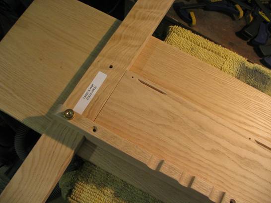
1) Temporarily attach the right notched board to the back of the main foot with a carriage bolt and thumb screw. This will help properly position the notched board on the back of the main board. Apply glue into each of the six (6) biscuit grooves on the edge of the right notched board and in the matching grooves on the right side of the main board & & insert a biscuit into each of the grooves on the right side of the main board. Run a 1/8″ wide bead of glue along the entire length of the right notched board biscuit-grooved edge.


2) Position the right notched board over the right side of the main board as illustrated and press into place. Adjust the position of the notched board along the length of the main board until the top of the front foot is firmly butted squarely against the end of the main board.
3) Use six (6) #8 x 2″ wood screws to secure the notched board to the main board. Additional clamping along the notched board is recommended to insure a tight glued joint. Remove the carriage bolt and the main foot from the assembly and thoroughly wipe excess glue from wood surfaces with a damp cloth, rinsing often.


4) Repeat step 1 using the left notched board.
5) Temporarily put the completed leg assembly between the notched boards in the “closed” position against the back of the mainboard and insert the leg swivel dowel through the right notched board & through the leg assembly. Adjust the position of the left notched board along the main board until the dowel can be pushed into the matching hole in the left notched board and the top of the front foot is firmly butted against the end of the main board.

6) Clamp and use six (6) #8 x 2″ wood to secure the left notched board to the main board. Additional clamping along the notched board is recommended to insure a tight glued joint. Remove the carriage bolt, main foot and the leg assembly and thoroughly wipe excess glue from wood surfaces with a damp cloth, rinsing often.

SEAT ASSEMBLY:
1) On a flat surface, space the two seat sides apart in the inverted position the approximate width of the seat front face and use the 2 seat dowels as an alignment aid (DO NOT GLUE) by inserting them through BOTH seat sides. Make sure the (shorter) dowel labeled “1” is in the front and that the numbered end matches the number label on the seat side. Rotate the seat front dowel until the holes are aligned with the holes on the bottom edges of the seat sides. Use two (2) #6 x 1″ wood screws to secure the front seat dowel to the seat sides.


2) Turn the assembly over to the upright position & apply a 1/8″ bead of glue to each front edge of the seat sides. Insure proper orientation of the seat front face and use four (4) #8 x 1-1/4″ wood screws to secure the seat front face to the ends of the seat sides. (TIP – After the glue is dry, sand the edges of the front face flush with the sides before proceeding to step 3)

3) Apply a 1/8″ bead of glue across the bottom of the REAR seat plank along the screw holes on each end and align with the screw mounting holes on each side. Use four (4) #8 x 1-1/4″ wood screws to secure the rear seat plank to the top of the seat sides.

4) Fasten the center and front seat planks to the tops of the seat sides as in step 3. NOTE: Prior to attaching the front seat plank, apply a 1/8″ bead of glue along the top edge of the seat front face. Additional clamping may be helpful to insure tight joints. Wipe excess glue from wood surfaces with a damp cloth, rinsing often.


STEP ASSEMBLY:
1) On a flat surface, space the two step sides apart in the inverted position the approximate width of the step front face and use the step & footrest dowels as an alignment aid (DO NOT GLUE) by inserting them through BOTH step sides. Rotate the (18″ long) footrest dowel until the holes are aligned with the holes on the bottom edges of the step sides. Use two (2) #6 x 1″ wood screws to secure the footrest dowel to the step sides.


2) Turn the assembly over to the upright position & apply a 1/8″ bead of wood glue to each of the front ends of the step sides. Insure proper orientation of the step front face and use four (4) #8 x 1-1/4″ wood screws to secure the step front face to the ends of the step sides.


3) Apply a 1/8″ bead of glue across the bottom of the step plank along the screw holes on each end and along the top edge of the step front face. Insure proper orientation of the step plank and use four (4) #8 x 1-1/4″ wood screws to secure the step plank to the top of the step sides.

Additional clamping may be helpful to insure tight joints. Wipe excess glue from wood surfaces with a damp cloth, rinsing often. (TIP – After the glue is dry, temporarily remove the footrest dowel and sand the edges of the front face & step plank flush with the step sides)


FINAL ATTACHMENT OF THE LEG ASSEMBLY:
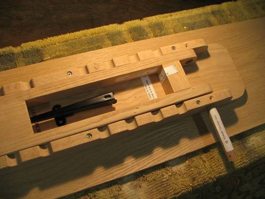
1) With the hinge in the folded position and the two attachment brackets swiveled to their extended positions, orient the hinge inside the leg with the joint of the hinge pointing toward the leg square spacer block. Now attach the LONG section of the hinge to the hinge support board with two #8 x 1/2″ screws at the 2 predrilled holes.

2) Place the leg assembly in position between the notched boards and align the dowel holes. Before pushing the swivel dowel in place, be sure to put a plastic washer between the leg and the adjacent notched board.

3) Use two #6 x 1″ screws to secure the leg swivel dowel to the notched boards.

4) Once the leg is attached, with the hinge still folded and the attachment bracket extended, mark the correct location for the main board hinge bracket attachment holes and center punch for starting. Attach the hinge to the main board with the remaining two #8 x 1/2″ screws.


If you purchase a CATSPERCH TM “Frazier Pro” Observing Chair Kit, I’m confident that you will find the assembly process enjoyable and that the building experience will enhance your enjoyment at the eyepiece.

Thanks for your time and interest in the
CATSPERCHTM “Frazier Pro” Observing Chair.
Clear Skies,
Ron Burrows
Owner/Craftsman, Wood Wonders. Inc.
Pinckney, Michigan